
Bézier Curves
I recently started toying with Processing and generative art, and in this little journey I’ve come across a specific method for curve drawing called the Bézier Curve. It is a parametric curve that is widely used in computer graphics, almost everywhere you need to draw curves: digital typography, vector graphics, illustration software (Adobe Illustrator, Inkscape), animation, etc.
This curve has a very interesting mathematical definition (it also has a recursive definition) and can be defined for any degree n. For a very good overview of the mathematics, related algorithms and more applications check A Primer on Bézier Curves. In this post I used the basic one provided in the Processing API, which is basically a Cubic Bézier Curve, i.e. has two anchor points and two control points. In the image shown below the points 1, 4 are the anchor points and 2, 3 are the control points.
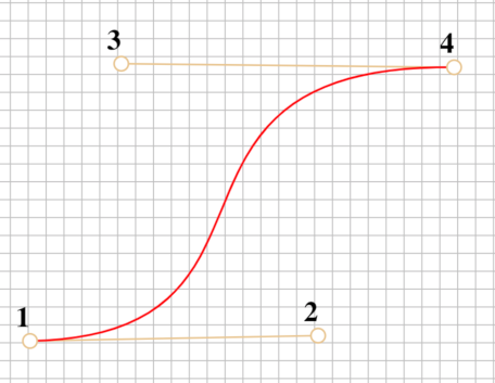
In processing the method is simply called bezier, but its signature can receive different parameters. For the current sketch of the post I used this configuration:
bezier(x1, y1, cpx1, cpy1, cpx2, cpy2, x2, y2);
//x1, y1  Coordinates of the curve’s starting point - equivalent to point `1`
//cpx1, cpy1  Coordinates of the first control point - equivalent to point `2`
//cpx2, cpy2  Coordinates of the second control point - equivalent to point `3`
//x2, y2  Coordinates of the curve’s ending point - equivalent to point `4`
Building a basic shape
First and foremost, in Processing we can actually continuously change the parameters to get a sense of the behavior of the curve. By altering both control points using alternating functions (in this case sin and cos) we see how the control points (the middle red points) affect the overall curvature of the shape. Inside the draw loop I change the coordinates with:
  cpx1 += 2*sin(0.005*millis());
  cpy1 += 2*sin(0.005*millis());
  cpx2 += 2*cos(0.005*millis()); // changed here to see a different cycle
  cpy2 += 2*sin(0.005*millis());
To generate a basic shape I first define the “center”, which is just a fancy name for where all the initial anchor point of the Bézier curve will start. To build the “flowers” shown at the title image we need to define:
- The control points of each “petal”;
- The movement function of the control points;
- The symmetrical rotation to generate the petals;
- The number of petals;
To actually define the control points, I experimented with different movement functions and settled on specific modifications to the basic trigonometric functions sin and cos. These functions are really useful because they’re periodic and naturally represent a “frequency”. By determining the “amplitude” and the “frequency” of each function we can create personalized shapes for the petal. In this case I defined a base offset value $v$ for the horizontal coordinates and we can obtain the time variable $t$ of the animation. We have two anchor points, $(x0, y0)$ and $(x1, y1)$. The vertical component of both control points is defined by $-|y1*sin(t)|$, while the offset for the horizontal component is defined as $\frac{v}{2} + |1.5v * sin(t)|$ for the first control point and $\frac{v}{2} + |1.5v * sin(t + \frac{2\pi}{3})|$.
In the image below, the actual function that dictates the path of the control points is shown in red and the “center” point is shown is black.
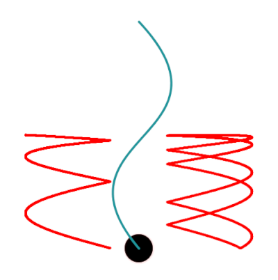
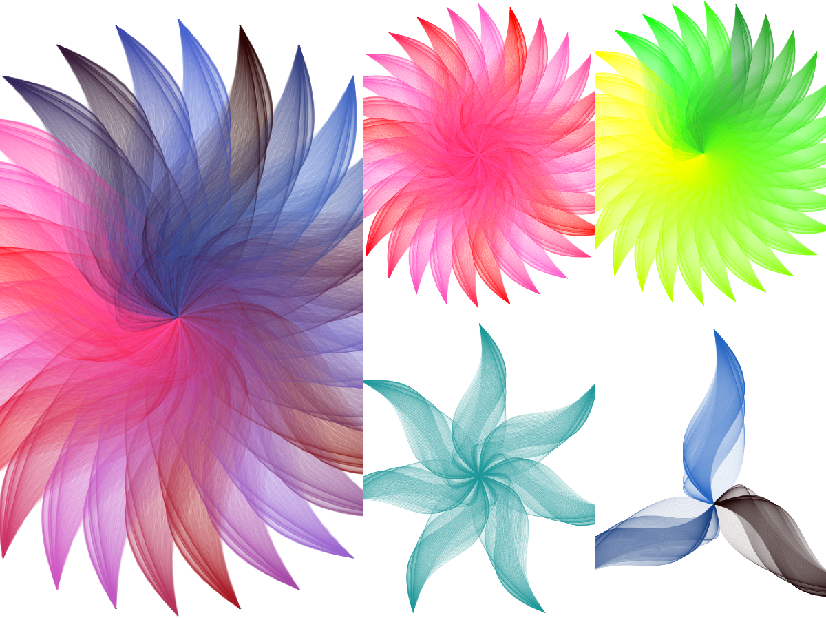
If we add an alpha level to the color (transparency) and let Processing continuously plot the curve we get this nice shape:
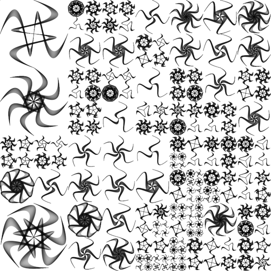
It’s now easier to add multiple petals: We get the number $N$ of petals and we partition our angles by this number, and for each petal $i$ its base angle will be $i\cdot \frac{2\pi}{N}$; Using rotate with this angle we repeat the same process N times and generate a “flower”. We can also explore the coloring of each petal, like making the colors be proportional to the angle, to the number of the petal, or completely random. Here are some examples of a collection of generated flowers with different number of petals and different coloring procedures:
The Grid
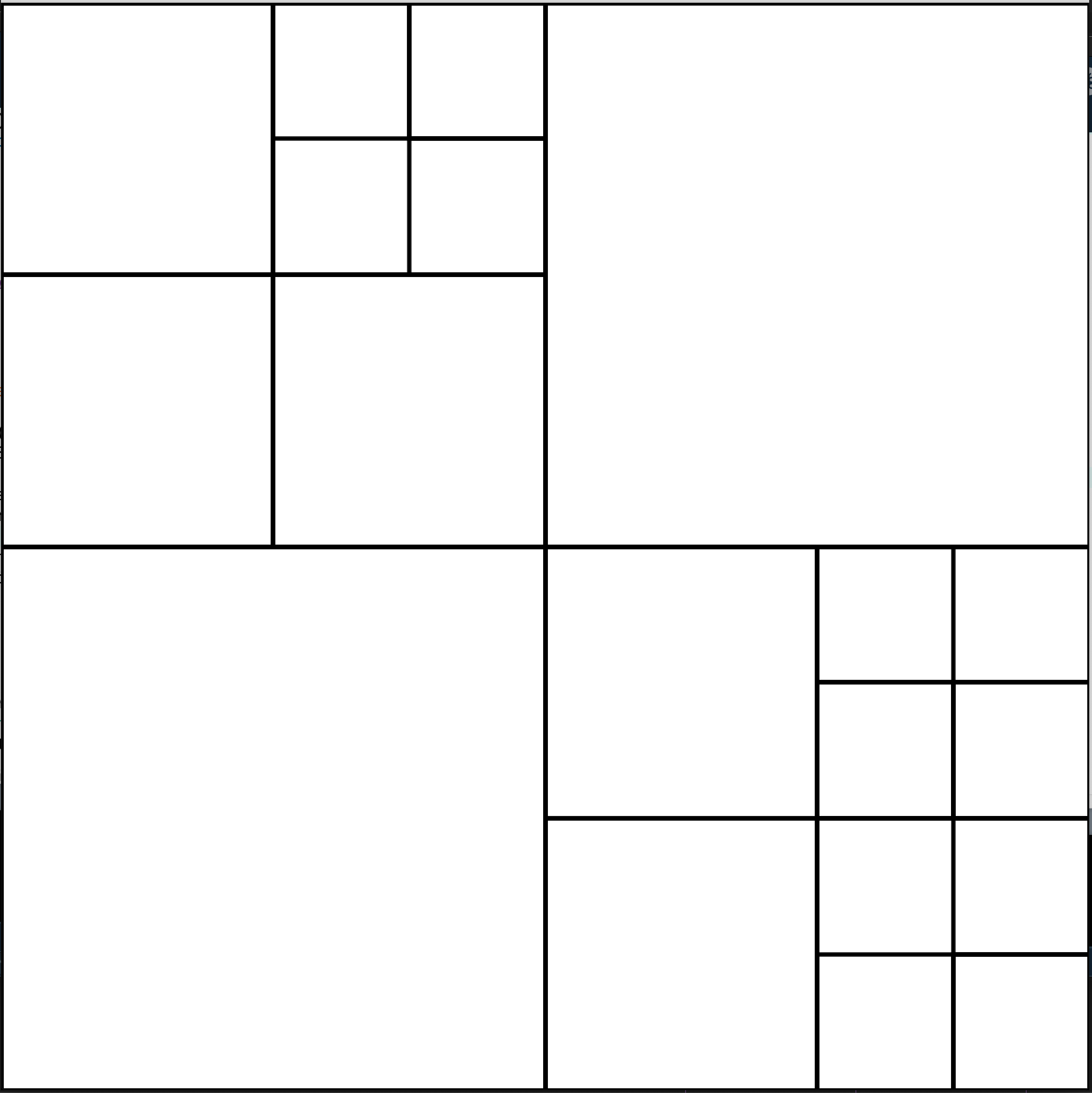
Now, each of these flower objects is encapsulated into an object, and we can change the center of each object, while maintaining the overall behavior of the shape. To create an interesting effect, I divided the canvas into a grid of squares, and using recursion each square is also subdivided further into more squares.
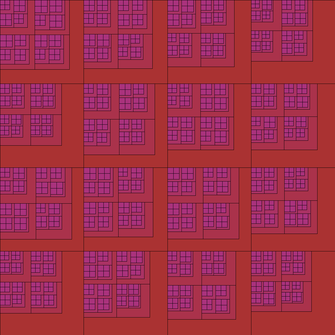
In each new grid the width of the square is a proportion of the width of its “father”, and when we achieve the determined maximum depth of the recursion the width has a random variation to create more interesting results. Also, each grid has a chance to generate or not a new grid, so this means we don’t always get the complete grid, and also that each time we run the script the results will be different.
Finally, we make the width of each flower conditional on the width of the square that circumscribes it, and the center of this square will also be the center of the flower.
The Final Product
There is a lot possible improvements here, like creating a nice color pattern, changing the color of each petal, making the colors proportional to the size of the flower, adding more randomization for the control points parametric equations, etc. This is just to show one possible result :D. I started to add these sketches in the repo art_ificial in my GitHub, so you can find the code for this specific example here!.